
Spice4qucs subcircuits, macromodels and device libraries. DC Example 2: Variation of power dissipation with varying DC input voltage.
Qucs examples download simulator#
To illustrate the performance of this emerging GPL simulator a number of examples taken from DC to RF are described. DC Example 1: Calculating circuit input resistance and power dissipation in a resistor. This paper outlines the structure and simulation capabilities of the Qucs simulator. A power electronics simulation example A MOSFET switch circuit with an inductive. Recent improvements to the Qucs/ADMS interface now allow a well defined procedure for VerilogA model construction. Qucs an Introduction to the New Simulation and Compact Device Modelling. These include, traditional subcircuits, equation defined devices and VerilogA compact models generated using the ADMS compiler. The package is equipped with a range of device and modeling features which allow fast prototyping of experimental compact device and circuit. Versions are available for most of the popular computer operating systems. It is one of the GPL simulators supporting VerilogA compact model standardization. Drag'n'drop component into symbol editor. Ruler in layout editor with right mouse button. Font size independent from screen density. Markers in Smith charts can display impedance etc. Besides many bugfixes, the new version exhibits the following new features: Create user library from SPICE and SnP files. Qucs is an open source circuit simulator with extensive device and circuit modeling capabilities. QucsStudio Version 4.2.2 is available now. The zone-based approach yields a flexible device model that is both quantitatively accurate and easy to employ in system level simulators.

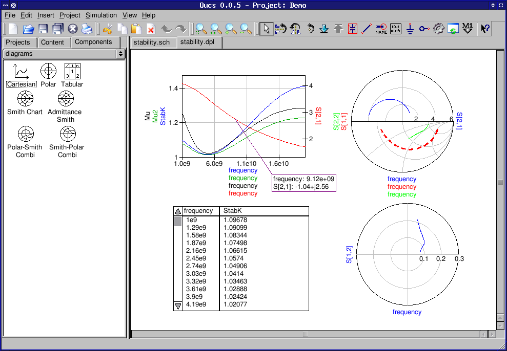
s-parameter analysis, gain/stability/noise circles, Touchstone. The physics-based approach produces a compact model that can easily be formulated to include all pertinent physical phenomena known to affect device performance. Examples transient analysis, oscillators, peak detectors, periodic steady-state analysis etc. The various zones are described with a simplified set of equations, and the zones are then linked to form the complete model. The zone-based approach divides the device into zones based upon operational physical phenomena. The approach starts from fundamental physical principles and produces a model that accurately describes the dc and RF performance of the device. In this work a zone-based approach to physics-based compact model development is described. alternate approach is to derive the model from fundamental physics, which permits the model to be used in device design as well as circuit applications. This requires that the device be fabricated and characterized before the model can be determined. The most commonly used models are not derived from basic physical fundamentals, but are rather determined by parameter extraction techniques from experiment. Oscillators, peak detectors, periodic steady-state analysis etc.Equivalent circuit field-effect transistor models (compact models) are extensively used in integrated circuit design and manufacture. (Drag’n’Drop into project list or via menu: Project → Extract Package…) DC analysis While some examples have been included in this story to demonstrate some of the abilities of Qucs. It also provides semiconductor-based components and models such as PMOSFETs, MOSFETs, op-amps, diodes and many more.
Qucs examples download archive#
They are archive files that are decompressed by QucsStudio. Qucs comes with a huge array of components and models including HICUM, BSIM2, BSIM3 and BSIM6 to list a few. The following files contain circuits that demonstrate the functionality of simulator and GUI.


 0 kommentar(er)
